 ]]>
]]>
Make+ First Meetup
April 19th, 2013 § 0 comments § permalink
ARTv5 Electronics Design
January 15th, 2011 § 0 comments § permalink
ARTv4 to have interesting, pseudo-intelligent behaviors (and not running out of SRAM which causes it to reset randomly…), I’m also working on the next generation electrical design for ART… I’m naming the bundle of software and electronics ARTv5. The plan is to support more infrared and ultrasonic sensors with an RF transceiver for sending telemetry information. I also want to start producing and using PCB boards to get away from the fragile breadboards. More specifically, these PCB will take the form of Arduino-shields that I can stack on top of each other. The plan right now is to create three boards that are stackable:
- One for the ultrasonics sensors (front, rear, left, right);
- One for the infrared sensors (front, rear, left, right);
- One with four connectors to ultrasonics sensors, infrared sensors, motors control in addition to the connector for the RF transceiver.
- Ultrasonics sensors shield: 10 wires (1 VCC, 1 GND, 4 echos, 4 triggers);
- Infrared sensors shield: 6 wires (1 VCC, 1 GND, 4 signals);
- RF transceiver: plugs into two 9×2 headers (1 VCC, 1 GND and the SPI wires);
- Four control motor wires for the H-bridge (used right now to connect directly to the RF transmitter as a hack).
- 1xGeneric female header – 10 pins;
- 1xGeneric female header – 2 pins;
- 2xGeneric female header – 4 pins;
- 1xGeneric female header – 6 pins.
ART Telemetry wireless solution
January 9th, 2011 § 2 comments § permalink
Been researching wireless solutions to transmit in real-time sensor and decision information from ART in addition to possibly enabling minimal controls (on/off/behavior switch) and perhaps even wireless firmware updates.
My criteria:
- Low-cost (<200RMB, preferably <100RMB)
- Simplex or half-duplex OK
- Low-bandwidth (>1,200 bit/s)
- Low-power (<100 mAh)
- Medium-range (500m-1000m)
- TTL or SPI interface
One of the main issue is that I cannot find a clear reference to the spectrum allocation in China (The US has a very convenient Frequency Allocations Chart: http://en.wikipedia.org/wiki/Frequency_allocation).
I know that 2.4Ghz is good worldwide (such as what the Nordic nRF240L uses) but that has a very limited range (50m-100m). So is Bluetooth and to a certain degree Wifi (and they are pretty expensive too).
There are these:
- PTR8000+ [Nordic nRF905 (433/868/915MHz)]
- Laipac Tech RF 900DV(900 mhz)
- Laipac ASK Transmitters (315 mhz)
- Databridge
- http://www.starmanelectric.com/OrderDataBridge/tabid/71/Default.aspx
- http://www.starmanelectric.com/LinkClick.aspx?fileticket=REf/38lk/L4%3d&tabid=75&mid=456
- Expensive (87$USD) and not available here?
- JZ871 Data RF transceiver for wireless telemetry system (433 MHz or 868Mhz/915Mhz)
- http://www.alibaba.com/product-gs/252550553/RF_data_transceiver.html
- http://www.jizhuo.com/download/product_images/f/cn_f__101.pdf
- I’m guessing if Alibaba is selling it, it’s ok in China? Or is it exactly just an export product?
Last one actually looks better than the Nordic on paper, but from what I gathered the price is pretty high. I wonder about the price and why I can’t find it on Taobao…
]]>
新车间开放日:休闲机器人的时代 Robot Contest Kick Off- Xin Che Jian Open House: the coming of entertainment robots
January 7th, 2011 § 0 comments § permalink
 新车间开放日:休闲机器人的时代
时间: 2011年元月十六日,下午一点到五点
地点:徐汇区永嘉路50号新单位(近陕西南路)
费用: 免费
随着数字零件价格的降低加上丰富的开源机器人软件,DIY机器人已经可以当做事一个假日的休闲活动。这次的新车间开放日我们将介绍几个会员DIY的机器人和介绍一个将要举办的积极人竞赛。如果你对机器人有兴趣,请在这个周日加入我们,一起了解现代机器人的发展,一起讨论如何玩机器人。如果有小孩的话,非常欢迎他们一起来参加这个的活动。
– 关于HC Robot
http://code.google.com/p/hcrobot/
– 关于A.R.T.
http://xinchejian.com/?p=289
在这里注册
Robot Contest Kick Off- Xin Che Jian Open House: the coming of entertainment robots
Time: 13:00 – 17:00, Jan 16, 2011
Location: Xindanwei, 50 Yongjia Rd
Cost: Free, Open house
Building robots is fun and building robots to race is doubling the fun! The era of robot building as hobby has come and we plan to celebrate the beginning of this era with a festive robot contest. At this Xin Che Jian open house, we will present a few home built robots and the plan for a contest for discussion. Come and see how you can get involved! If you are a parent, bring the kids! We are sure they will love the robots!
Robots on site:
– HC Robot: open source home help robots
http://code.google.com/p/hcrobot/
– A.R.T.
http://xinchejian.com/?p=289
Register for the event here]]>
新车间开放日:休闲机器人的时代
时间: 2011年元月十六日,下午一点到五点
地点:徐汇区永嘉路50号新单位(近陕西南路)
费用: 免费
随着数字零件价格的降低加上丰富的开源机器人软件,DIY机器人已经可以当做事一个假日的休闲活动。这次的新车间开放日我们将介绍几个会员DIY的机器人和介绍一个将要举办的积极人竞赛。如果你对机器人有兴趣,请在这个周日加入我们,一起了解现代机器人的发展,一起讨论如何玩机器人。如果有小孩的话,非常欢迎他们一起来参加这个的活动。
– 关于HC Robot
http://code.google.com/p/hcrobot/
– 关于A.R.T.
http://xinchejian.com/?p=289
在这里注册
Robot Contest Kick Off- Xin Che Jian Open House: the coming of entertainment robots
Time: 13:00 – 17:00, Jan 16, 2011
Location: Xindanwei, 50 Yongjia Rd
Cost: Free, Open house
Building robots is fun and building robots to race is doubling the fun! The era of robot building as hobby has come and we plan to celebrate the beginning of this era with a festive robot contest. At this Xin Che Jian open house, we will present a few home built robots and the plan for a contest for discussion. Come and see how you can get involved! If you are a parent, bring the kids! We are sure they will love the robots!
Robots on site:
– HC Robot: open source home help robots
http://code.google.com/p/hcrobot/
– A.R.T.
http://xinchejian.com/?p=289
Register for the event here]]>
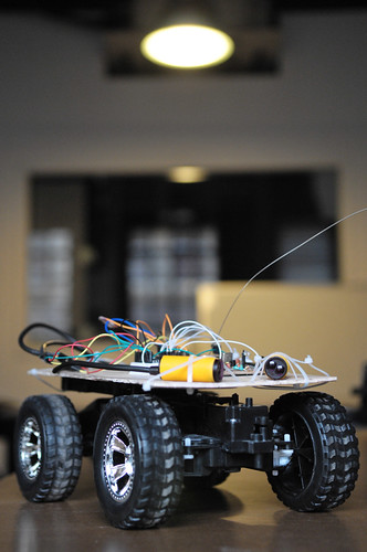
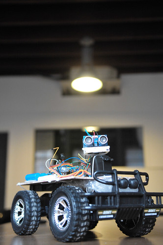
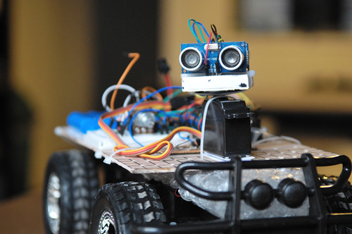
A.R.T. Glamour
January 6th, 2011 § 1 comment § permalink
 ]]>
]]>
CPLD
January 3rd, 2011 § 0 comments § permalink
about adding more ultrasonic sensors connected to the Arduino , I’m looking at implementing some of the logic in digital logic gates external to the Arduino… After researching this for a while, I’ve stumbled on something half-remembered from university: FPGA and CPLD. CPLD seems particularly well suited and although my first few applications would be very simple, I’m thinking many of the real-time stuff needed by robotics (sensor processing, PWM control) would be well served by CPLD hardware designs. So I’m thinking about buying these two things: Xilinx Platform Cable USB (programs Xilinx CPLD/FPGA) 228.00元 Expensive but can be used to program very many CPLD XILINX XC9572XL in a DIP40 package: 42.00元 Very convenient packaging that will work with the breadboard in addition to having, from the datasheet, “1,600 usable gate” (about 100 times what I need right now for the ultrasonic sensor selector….) These are some useful links about CPLD: http://bitcycle.org/electronics/1st_CPLD_project/ CPLD’s have a number of useful properties: A small CPLD can replace the function of a handful standard logic IC’s (74xxx etc), a large CPLD can replace the function of hundreds of these. The result is a drastic reduction in circuit board space, and power consumption. The logic function performed by a CPLD is user-programmable. Normally it can be erased, and re-programmed many times. That is: can be changed on-the-fly. What used to be hardware (wires / connections), becomes software (hardware description language). Which input or output pin is used for what signal, can be chosen by the user. This helps to simplify circuit board layout. Many CPLD’s (not all) are in-system programmable. That is: the function of a circuit can be changed after it has been built, without re-wiring or replacing components. The price of CPLD’s (and other programmable logic devices) has come down enough to make their use feasible in many designs. These advantages come at a cost: complexity. While it is simple to connect a few logic gates using 74xxx IC’s, a significant barrier has to be overcome to do the same with a CPLD. This barrier consists of required hardware, software & knowledge. However: once this barrier has been overcome, it becomes easier to modify a design. Also one can tackle more complex designs, that would be (near) impossible using standard logic. http://www.mouldy.org/using-cplds-and-fpgas-in-hobby-electronics As an example, my recent H-bridge controller was implemented on a PIC microcontroller. This worked well enough, but performance was suboptimal, and some nasty hacks were required because the I/O lines couldn’t do exactly what I wanted. With a CPLD, I have dedicated hardware to implement things like the PWM controller, H-bridge logic and I2C interface; these subsystems would have operating frequencies in the hundreds of megahertz, instead of kilohertz. A few years back, there were crippling problems that prevented hobbyists from making use of CPLDs and FPGAs. Just about all of these have been remedied. http://www.triplespark.net/elec/pdev/cpld/ CPLDs don’t replace microcontrollers and vice versa; in fact, they complement one another very well: CPLDs are good if you need speed as long as the complexity of the task is limited. In contrast, microcontrollers can do lots of fancy things but at slower speed. http://www.seattlerobotics.org/encoder/200006/cpld.htm PLDs or Complex Programmable Logic Devices are the next extension to the PLD market. They are today’s technological stepping stone between a handful of discrete gates and a full custom design. What’s more, the silicon manufacturers are so interested in beginning engineers down the path of brand loyalty, that one & two quantity pricing is around five dollars for surprisingly powerful devices. At the same time, entry level software development tools have evolved from multi-thousand dollar price tags to free (Public Domain) Inter Net downloads while at the same time, continuing to gain in power. https://www.seas.upenn.edu/~ese201/vhdl/vhdl_primer.html The highest level of abstraction is the behavioral level that describes a system in terms of what it does (or how it behaves) rather than in terms of its components and interconnection between them. A behavioral description specifies the relationship between the input and output signals. This could be a Boolean expression or a more abstract description such as the Register Transfer or Algorithmic level. As an example, let us consider a simple circuit that warns car passengers when the door is open or the seatbelt is not used whenever the car key is inserted in the ignition lock At the behavioral level this could be expressed as, Warning = Ignition_on AND ( Door_open OR Seatbelt_off) The structural level, on the other hand, describes a system as a collection of gates and components that are interconnected to perform a desired function. A structural description could be compared to a schematic of interconnected logic gates. It is a representation that is usually closer to the physical realization of a system. ]]>
ART Platform v3, Control v4 and the future platform v4
January 3rd, 2011 § 3 comments § permalink
many iterations of both the software (the controller) after updating the platform (sensors+chassis) itself to have an additional ultrasonic sensor looking backward. So now, when I rotate the ultrasonic sensor, I read values in front (right side, angle looking right, looking forward and at angle to the left) and towards the back (left-side, side angle looking backward towards the left, angle straight on towards the back and angle looking backward towards the right). So six values in total… Having the servo rotate the sensors is necessary right now so as not to go over budget on the digital pins of the Arduino Dueminalove board as each of the two sensors require two signal cable (one for trigger and one for echo). I’ve done many changes and many tests but I’m not yet satisfied with the controller for that particular configuration and I still have ideas that I need to implement to make the robot behavior interesting… However, in the meantime, I’m also preparing for the next platform. I’m thinking of designing a circuit to select one ultrasonic sensor at a time out of four. Since two sensors cannot be triggered simultaneously (they would interfere with each other) I would want to trigger one at a time and then wait for the echo. To help with that task, I’ve discovered two wonderful OpenSource software:
- Fritzing: a very good design software that lets you design breadboard, schematic and final PCB layout with a library of parts (or very easy to create custom parts) in an optimized workflow
- Logic Gate Simulator: create and test logic gates design
ARTv2 goes Ultrasonic!
December 30th, 2010 § 1 comment § permalink
Me: …since we don’t have many working sensors, I’m waiting for the ultrasonic sensors we ordered… BTW, Xu, any news about them? Xu: Oh, they’re at my desk! Me: screams like a little girl Xu: … ok, I’ll go get them now… So yeah, I finally got my 10 (!) ultrasonic sensors (HC-SR04) this evening, just in time as I had worked out how to control the servo to do sensor sweeps (left and right on 180 degrees). BTW, if you’re a Xinchejian member, please feel free to borrow one or two to try them out. They’re affordable (37RMB on Taobao or 5.60$USD), ridiculously easy to install and seem to work as advertised, although I haven’t benchmarked much. I’ve also spent quite a bit of time this evening on a reasonably workable controller with a state machine but only had time to test it once before I had to call it a day. I can probably use more sensors (on the sweeper, sideways, looking backward), but I’m thinking that I really need to combine them with infrared sensors as there’s a longer delay than infrared in detecting obstacles and they can work at angles simultaneously. Anyway, more testing and experiments are in order. [gallery]]]>
A.R.T. Version 2 (with instructions!)
December 30th, 2010 § 0 comments § permalink
Today I built a second new A.R.T. to test new configurations.
It’s also because it is a bit frustrating not to have a working version at all times for demos while I’m trying out new mechanical layouts… I took the opportunity to write down a detailed list of parts, tools and steps that I’ve checked in to github (note that I have not finished as I still have to solve the ranging sensor and write a new program):
https://github.com/rngadam/ART/blob/master/ART_Control3/BUILD.txt
See gallery for pictures…
[gallery link="file"] ]]>First successful autonomous run of A.R.T.
December 27th, 2010 § 1 comment § permalink
const int FORWARD =  2;
const int REVERSE =  3;
const int LEFT = 4;
const int RIGHT =  5;
const int INFRARED_FORWARD = A0;
const int INFRARED_REVERSE = A1;
const int MINIMUM_INFRARED_READING = 500;
int current_reverse = LEFT;
int alt_forward = RIGHT;
char current_state;
void setup() {
  pinMode(FORWARD, OUTPUT);
  pinMode(REVERSE, OUTPUT);
  pinMode(LEFT, OUTPUT);
  pinMode(RIGHT, OUTPUT);
  pinMode(INFRARED_FORWARD, INPUT);
  pinMode(INFRARED_REVERSE, INPUT);
  Serial.begin(9600);
}
char update_state(char state, int reason) {
  char previous_state = current_state;
  if(state != current_state) {
    current_state = state;
    Serial.print(current_state);
    Serial.println(reason);
  }
  return previous_state;
}
void loop(){
    // always check if we can go forward
    int value = analogRead(INFRARED_FORWARD);
    if(value >= MINIMUM_INFRARED_READING) {
        // maybe we were correcting, so check that
        char last_state = update_state('F', value);
        digitalWrite(current_reverse, LOW);
        digitalWrite(REVERSE, LOW);
        if(last_state == 'R') {
          // we just successfully exited a bad loop, turn for a bit for half a second
          digitalWrite(alt_forward, HIGH);
          digitalWrite(FORWARD, HIGH);
          delay(1000);
          digitalWrite(alt_forward, LOW);
        }
        digitalWrite(FORWARD, HIGH);
    } else {
      // otherwise, still correcting, keep off
      digitalWrite(FORWARD, LOW);
      // we want to try to find an alt path
      int value = analogRead(INFRARED_REVERSE);
      if(value >= MINIMUM_INFRARED_READING) {
        //still have some ability to go backward
        update_state('R', value);
        digitalWrite(current_reverse, HIGH);
        digitalWrite(REVERSE, HIGH);
      } else {
        // whooaah, even backward is not possible, we're stuck
        digitalWrite(current_reverse, LOW);
        digitalWrite(REVERSE, LOW);
        update_state('S', value);
      }
    }
}
Wins:
- Wooden board and tie-wraps work exceptionally well to prototype the physical arrangement
- Using the breadboard to prototype the electronics also works well
- The Arduino “Vin” to provide current in the board header works very well (and can seamlessy switch between USB and that without resetting!)
- Sticking the RF transmitter board directly on the robot and controlling the motors with that from the Arduino works well
- The LED that comes on when an obstacle is detected by the infrared sensors is very useful for debugging (need to keep that in mind when using other sensors)
- It works!
- Uses Alkaline AA batteries (I want to switch to the exact same Rechargeable NiCad as the car uses)
- I spent too much time working with Sketchup instead of manually testing the mechanical design first (and then Sketchup)
- There’s not much around Xindanwei in terms of computer, electronic or small mechanical stores, so I should plan ahead to shop on Beijing road
- The infrared sensors that I found in the pile of stuff in Xinchejian work, but more like “on/off” sensors (don’t seem to have any linearity in the distance)
- No bumper (the infrared sensor was crashing into the walls…)
- Making an obstacle course big enough is annoying
- I had forgotten to make the holes to attach the sensors (more holes == better)
- No on/off switch so have to manually remove the connections to turn off power
- You can never have enough tie-wraps… We only had four at Xinchejian before I bought a pack of 500 for 15RMB (but really, worth about 5RMB)
- I need to learn how to solder… without blowing fuses…