April 18th, 2011 § § permalink
I Love My Job! 我热爱我的工作!
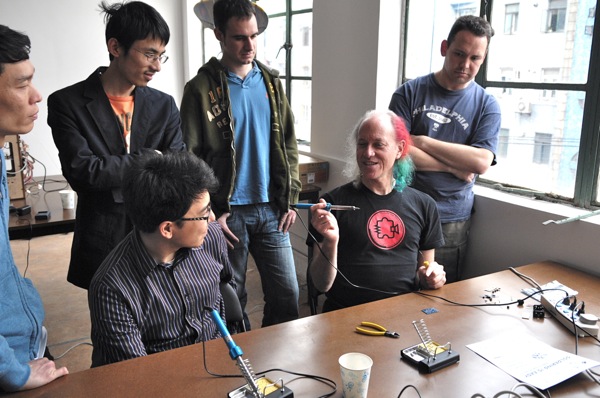
来自美国San Francisco的大牛黑客Mitch Altman呼吁我们去做自己想做的事,如果每个人都热爱他的工作,这样世界就会变的更美好!
Mitch Altman发明了TV-B-Gone(可以关掉任何电视的遥控器),他会发明这个遥控器是因为他发现自己和周边的人都是“电视控”,突然觉得自己浪费了太多宝贵的时间在做没有意义的事情。他说:“根据调查有80%的美国人花了一生中1/3的时间来做不喜欢的工作,花1/3的时间来睡觉(梦想自己想做而没做的事),然后把剩下的1/3时间花在看电视上”,所以他觉得这个社会需要改变对电视的依赖!他的TV-B-GONE一开卖就卖了20几万个,他也从爱好中赚了钱。 如果你不爱你目前的工作,那你就改花点时间好好的思考你想做什么,然后勇敢的朝着梦想前进!
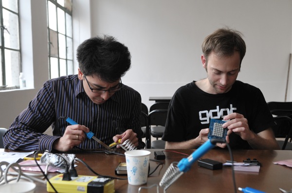
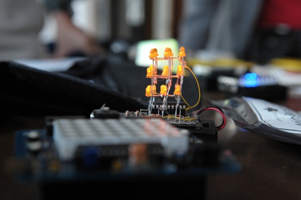
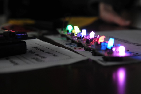
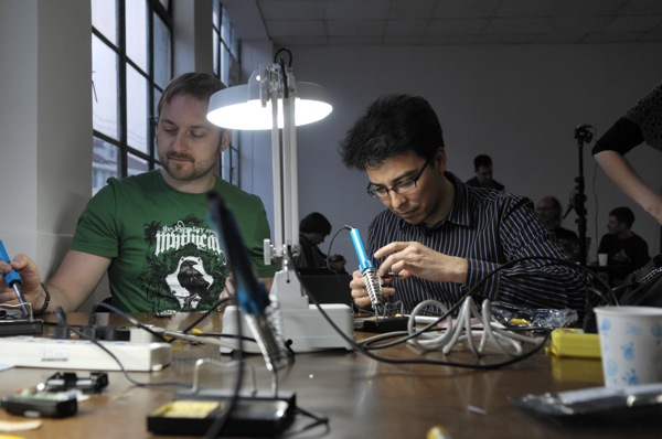
Mitch Altman来访新车间的活动照片:






]]>
March 26th, 2011 § § permalink
Aaajiao of Xindanwei gave a talk on what it took to run a space and his personal experience with making and hacking. XinCheJian goes well back with Xindanwei from working together on Scratch for Kids to incubating XinCheJian on 2F of YongJia Lu location.

]]>
March 14th, 2011 § § permalink
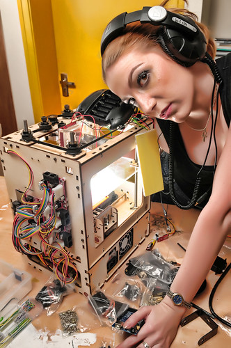
I shoot this a while back to promote Hackerspace but never get around to publish it. Strobist is the tinker of light and the hacker among photographers.
Some strobist setup info here:
- SB-600 inside the makerbot
- SB-800 on shoot-through umbrella to the camera right


]]>
March 14th, 2011 § § permalink
March 5th, 2011 § § permalink
#ym4-arduino-uno img
{
margin:5px;
padding:5px;
display:block;
}
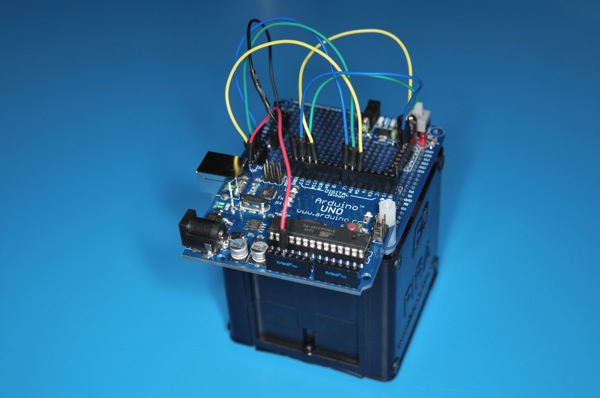
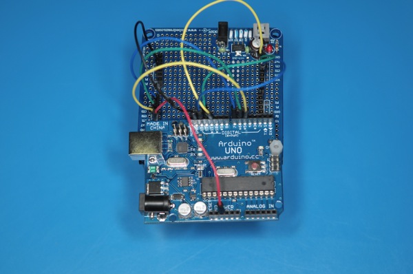
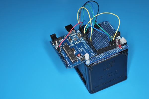
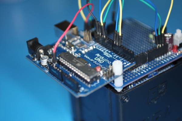
Another weekend night of hacking fun hooking up a Arduino Uno with YM4 robotic car from EmbeDream. The YM4 is a well designed FIRA compliant robot car with built in power supply. The left and right wheels are controlled independently and the built in feedback from wheels.
The break out board for the YM4 is easy to work with. The H-bridge control are CT1, CT2, and CT3. CT1 control the speed with PWM and CT2/CT3 decide the direction of the wheel. This is the same configuration for both wheels. The following is a quick sketch to get YM4 going forward.
#define RIGHT_CTRL_1 5
#define RIGHT_CTRL_2 6
#define RIGHT_CTRL_3 7
#define LEFT_CTRL_1 11
#define LEFT_CTRL_2 12
#define LEFT_CTRL_3 13
void setup()
{
 pinMode(RIGHT_CTRL_2, OUTPUT);
 pinMode(RIGHT_CTRL_3, OUTPUT);
 pinMode(LEFT_CTRL_2, OUTPUT);
 pinMode(LEFT_CTRL_3, OUTPUT);
}
void loop()
{
  digitalWrite(RIGHT_CTRL_2, 0);
  digitalWrite(RIGHT_CTRL_3, 1);
  analogWrite(RIGHT_CTRL_1, 128);
  digitalWrite(LEFT_CTRL_2, 0);
  digitalWrite(LEFT_CTRL_3, 1);
  analogWrite(LEFT_CTRL_1, 128);
}
Now, the TODO list
- Find a more secure way to protect the Uno board and protect it from bumping into objects when robot start to run
- Figure out how and where to attach sensors: ultrasonic distance and infra red for distance and obstacle sensing
]]>
February 25th, 2011 § § permalink
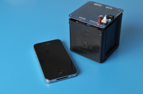
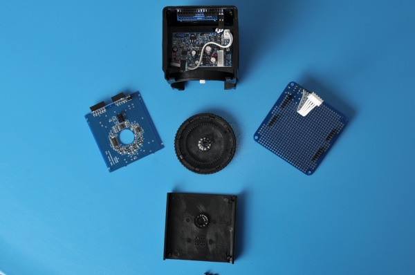
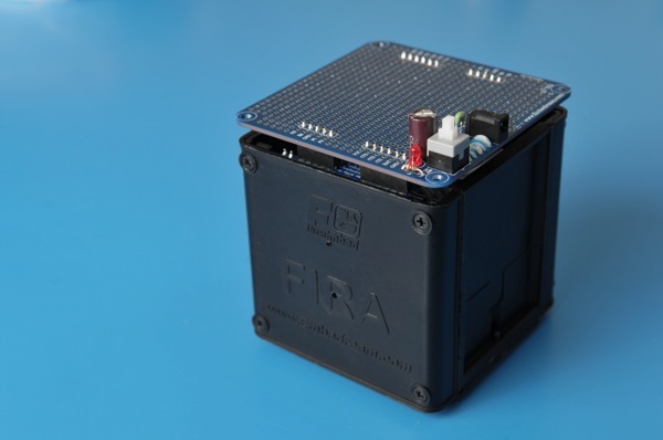
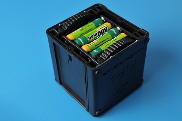
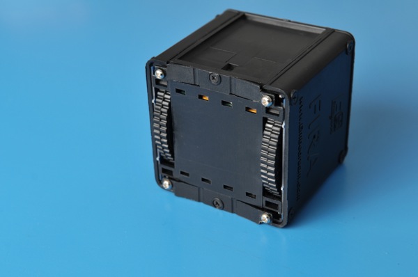
We received visitor from Nanjing based EmbeDream today. The gust come bearing gift of their open source FIRA bot. It’s of great design and I can’t not wait to try to hook it up to Arduino to have some fun! Here are some photos of the bot.
It’s small cube.
Take apart one side
]]>
January 17th, 2011 § § permalink
January 3rd, 2011 § § permalink
about adding more ultrasonic sensors connected to the Arduino , I’m looking at implementing some of the logic in digital logic gates external to the Arduino… After researching this for a while, I’ve stumbled on something half-remembered from university: FPGA and CPLD.
CPLD seems particularly well suited and although my first few applications would be very simple, I’m thinking many of the real-time stuff needed by robotics (sensor processing, PWM control) would be well served by CPLD hardware designs.
So I’m thinking about buying these two things:
Xilinx Platform Cable USB (programs Xilinx CPLD/FPGA) 228.00元
Expensive but can be used to program very many CPLD
XILINX XC9572XL in a DIP40 package: 42.00元
Very convenient packaging that will work with the breadboard in addition to having, from the datasheet, “1,600 usable gate” (about 100 times what I need right now for the ultrasonic sensor selector….)
These are some useful links about CPLD:
http://bitcycle.org/electronics/1st_CPLD_project/
CPLD’s have a number of useful properties:
A small CPLD can replace the function of a handful standard logic IC’s (74xxx etc), a large CPLD can replace the function of hundreds of these. The result is a drastic reduction in circuit board space, and power consumption.
The logic function performed by a CPLD is user-programmable. Normally it can be erased, and re-programmed many times. That is: can be changed on-the-fly. What used to be hardware (wires / connections), becomes software (hardware description language).
Which input or output pin is used for what signal, can be chosen by the user. This helps to simplify circuit board layout.
Many CPLD’s (not all) are in-system programmable. That is: the function of a circuit can be changed after it has been built, without re-wiring or replacing components.
The price of CPLD’s (and other programmable logic devices) has come down enough to make their use feasible in many designs.
These advantages come at a cost: complexity. While it is simple to connect a few logic gates using 74xxx IC’s, a significant barrier has to be overcome to do the same with a CPLD. This barrier consists of required hardware, software & knowledge. However: once this barrier has been overcome, it becomes easier to modify a design. Also one can tackle more complex designs, that would be (near) impossible using standard logic.
http://www.mouldy.org/using-cplds-and-fpgas-in-hobby-electronics
As an example, my recent H-bridge controller was implemented on a PIC microcontroller. This worked well enough, but performance was suboptimal, and some nasty hacks were required because the I/O lines couldn’t do exactly what I wanted. With a CPLD, I have dedicated hardware to implement things like the PWM controller, H-bridge logic and I2C interface; these subsystems would have operating frequencies in the hundreds of megahertz, instead of kilohertz.
A few years back, there were crippling problems that prevented hobbyists from making use of CPLDs and FPGAs. Just about all of these have been remedied.
http://www.triplespark.net/elec/pdev/cpld/
CPLDs don’t replace microcontrollers and vice versa; in fact, they complement one another very well: CPLDs are good if you need speed as long as the complexity of the task is limited. In contrast, microcontrollers can do lots of fancy things but at slower speed.
http://www.seattlerobotics.org/encoder/200006/cpld.htm
PLDs or Complex Programmable Logic Devices are the next extension to the PLD market. They are today’s technological stepping stone between a handful of discrete gates and a full custom design. What’s more, the silicon manufacturers are so interested in beginning engineers down the path of brand loyalty, that one & two quantity pricing is around five dollars for surprisingly powerful devices. At the same time, entry level software development tools have evolved from multi-thousand dollar price tags to free (Public Domain) Inter Net downloads while at the same time, continuing to gain in power.
https://www.seas.upenn.edu/~ese201/vhdl/vhdl_primer.html
The highest level of abstraction is the behavioral level that describes a system in terms of what it does (or how it behaves) rather than in terms of its components and interconnection between them. A behavioral description specifies the relationship between the input and output signals. This could be a Boolean expression or a more abstract description such as the Register Transfer or Algorithmic level. As an example, let us consider a simple circuit that warns car passengers when the door is open or the seatbelt is not used whenever the car key is inserted in the ignition lock At the behavioral level this could be expressed as,
Warning = Ignition_on AND ( Door_open OR Seatbelt_off)
The structural level, on the other hand, describes a system as a collection of gates and components that are interconnected to perform a desired function. A structural description could be compared to a schematic of interconnected logic gates. It is a representation that is usually closer to the physical realization of a system. ]]>
January 3rd, 2011 § § permalink
many iterations of both the software (the controller) after updating the platform (sensors+chassis) itself to have an additional ultrasonic sensor looking backward. So now, when I rotate the ultrasonic sensor, I read values in front (right side, angle looking right, looking forward and at angle to the left) and towards the back (left-side, side angle looking backward towards the left, angle straight on towards the back and angle looking backward towards the right).
So six values in total… Having the servo rotate the sensors is necessary right now so as not to go over budget on the digital pins of the Arduino Dueminalove board as each of the two sensors require two signal cable (one for trigger and one for echo).
I’ve done many changes and many tests but I’m not yet satisfied with the controller for that particular configuration and I still have ideas that I need to implement to make the robot behavior interesting…
However, in the meantime, I’m also preparing for the next platform. I’m thinking of designing a circuit to select one ultrasonic sensor at a time out of four. Since two sensors cannot be triggered simultaneously (they would interfere with each other) I would want to trigger one at a time and then wait for the echo.
To help with that task, I’ve discovered two wonderful OpenSource software:
- Fritzing: a very good design software that lets you design breadboard, schematic and final PCB layout with a library of parts (or very easy to create custom parts) in an optimized workflow
- Logic Gate Simulator: create and test logic gates design
For Fritzing, I also took the time to create a custom part for the HC-SR04 Ultrasonic Sensor. I’ve done so by first drawing vector graphics for the breadboard view, schematic view and PCB board in Inkscape. I then created a new part, imported the just created images and then placing connections “squares” overlaid on the imported images. Relatively easy, but I spent a lots of time getting the fonts right before discovering that the easiest way was to convert all text to paths (Path > Object to Path).
I’ve uploaded the HC-SR04 Fritzing part in the relevant
“user-contributed parts” bug if you need it.
For Logic Gate Simulator, I first wrote down the truth table for the sensor selector (“when pin1 and pin2 are at 1, send trigger signal to sensor4 and receive echo from sensor4”) and tested it, but I’m unsure on how to proceed next in terms of buying the necessary IC that would provide me with the AND/NOT logic gate that I need.
I also have to investigate how to change the simplistic Ultrasonic code that’s been provided with the sensors to instead generate interrupts so I don’t have to block the Arduino loop while waiting for the echo to come back. Same for getting the “stop now” button to actually work!
[gallery]
]]>
December 23rd, 2010 § § permalink
http://hackerspaces.org/wiki/Xinchejian]]>


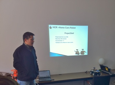
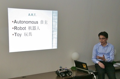 Then we have the introduction to the HCR robots by the presenter also named Ricky. HCR is an open source robot built to for home caring.
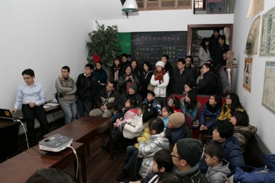
 And some random photos from the events.
 ]]>
]]>