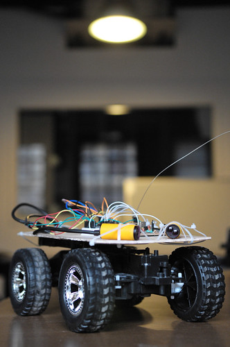
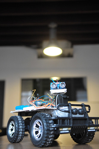
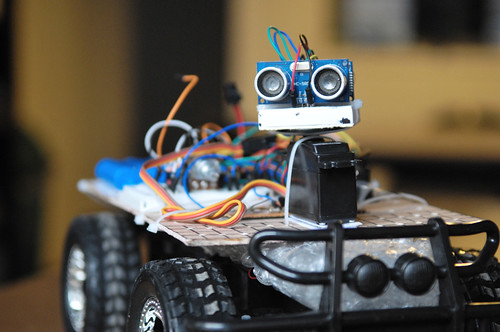
As I was trying to hook up the motor to Arduino, I realized that there wasn’t any H Bridge and it was way too cold to go out and get it. Hmm… I figure there must be some H Bridge on the control board I just rip out of the car.
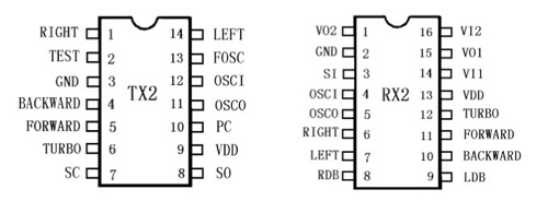
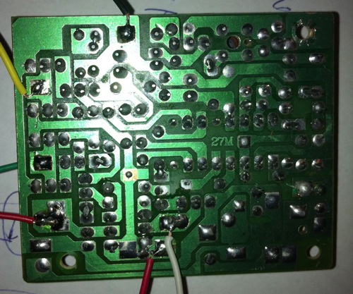 As I located the two H bridge on the board, I notice the RX-2 chip. Out of curiosity, I decide to google for this chip. To a pleasant surprise, I found RX-2/TX-2 Datasheet in Chinese and guide for exactly the board in the car and remote.
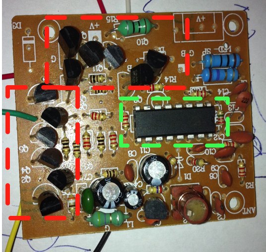
 Decide to replace RX-2 in the car with Arduino so the H-Bridge on board can be reused and the RF for the remote can still work. Still trying to figure out what I am going to do with those remote control signal. A few facts about RX-2/TX-2 chip I found is that the RC frequency can be adjusted by different resistance from 100K to 500K Ohm between OSCI/OSCO pins.
 ]]>
]]>
TX-2/RX-2: Heart of the cheap RC Toys from China
January 9th, 2011 § 12 comments § permalink
ART Telemetry wireless solution
January 9th, 2011 § 2 comments § permalink
Been researching wireless solutions to transmit in real-time sensor and decision information from ART in addition to possibly enabling minimal controls (on/off/behavior switch) and perhaps even wireless firmware updates.
- Low-cost (<200RMB, preferably <100RMB)
- Simplex or half-duplex OK
- Low-bandwidth (>1,200 bit/s)
- Low-power (<100 mAh)
- Medium-range (500m-1000m)
- TTL or SPI interface
- PTR8000+ [Nordic nRF905 (433/868/915MHz)]
- Laipac Tech RF 900DV(900 mhz)
- Laipac ASK Transmitters (315 mhz)
- Databridge
- http://www.starmanelectric.com/OrderDataBridge/tabid/71/Default.aspx
- http://www.starmanelectric.com/LinkClick.aspx?fileticket=REf/38lk/L4%3d&tabid=75&mid=456
- Expensive (87$USD) and not available here?
- JZ871 Data RF transceiver for wireless telemetry system (433 MHz or 868Mhz/915Mhz)
- http://www.alibaba.com/product-gs/252550553/RF_data_transceiver.html
- http://www.jizhuo.com/download/product_images/f/cn_f__101.pdf
- I’m guessing if Alibaba is selling it, it’s ok in China? Or is it exactly just an export product?
新车间开放日:休闲机器人的时代 Robot Contest Kick Off- Xin Che Jian Open House: the coming of entertainment robots
January 7th, 2011 § 0 comments § permalink
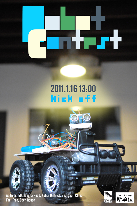 新车间开放日:休闲机器人的时代
时间: 2011年元月十六日,下午一点到五点
地点:徐汇区永嘉路50号新单位(近陕西南路)
费用: 免费
随着数字零件价格的降低加上丰富的开源机器人软件,DIY机器人已经可以当做事一个假日的休闲活动。这次的新车间开放日我们将介绍几个会员DIY的机器人和介绍一个将要举办的积极人竞赛。如果你对机器人有兴趣,请在这个周日加入我们,一起了解现代机器人的发展,一起讨论如何玩机器人。如果有小孩的话,非常欢迎他们一起来参加这个的活动。
– 关于HC Robot
http://code.google.com/p/hcrobot/
– 关于A.R.T.
http://xinchejian.com/?p=289
在这里注册
Robot Contest Kick Off- Xin Che Jian Open House: the coming of entertainment robots
Time: 13:00 – 17:00, Jan 16, 2011
Location: Xindanwei, 50 Yongjia Rd
Cost: Free, Open house
Building robots is fun and building robots to race is doubling the fun! The era of robot building as hobby has come and we plan to celebrate the beginning of this era with a festive robot contest. At this Xin Che Jian open house, we will present a few home built robots and the plan for a contest for discussion. Come and see how you can get involved! If you are a parent, bring the kids! We are sure they will love the robots!
Robots on site:
– HC Robot: open source home help robots
http://code.google.com/p/hcrobot/
– A.R.T.
http://xinchejian.com/?p=289
Register for the event here]]>
山寨与创新—从刚果河的鱼&韶山的灶房&创新的梦工厂谈起
January 6th, 2011 § 0 comments § permalink
OpenSourceCamp Shanghai上有很精彩对开源和山寨的讨论,王江川写了这篇相当有趣的文章。 — 这两日,看到大家在坛子里炒得确实很开锅,不时冒出一些新颖的单词来,什么云计算、创新工厂、开源商业模式,同时又似乎总被一个土的掉牙的词—“山寨”时不时搅和着。 耳边被山寨这个词浸濡许久了,今天,抽空进行点思考和梳理。 “山寨”,究竟何方神圣也? 从一开始的莫不关注,到身临其境,再至醍醐灌顶。不断地清晰和觉悟到,山寨本质上就是一种自然界创新精神与文化的代言。 国人发明各种辞藻的本事的确很强,乍一听,山寨,直愣愣就往水泊梁山108将而去。仔细寻思来去,竟然,极其地精准和绝妙,缘来,这背后其实是一回事情儿。 之前,看到一段探索频道的节目。 说的是一群勇于探险的科学家经过生死经历在刚果河考察而得出的一些发现。他们在刚果河中发现了很多之前不被人类所了解的不同鱼种,其中有些可能是新物种。我看到那些奇形怪状的鱼儿,有巨大凶猛的虎鱼,有像小手指那么大小的没有视力且出水就死的不明鱼种,有一种长着像大象鼻子模样的鱼儿,总之是稀奇古怪,像来自外星球。那群科学家似乎很兴奋,因为他们发现了新的基因宝库。对此奇异现象,他们做出了科学的分析:刚果河可能是世界上最深的河流,有一处地方居然深达230米,同时其深度和水流变化多端,形成很多个隔离开的区域。快速的流水和强大的急流制造了小型鱼类不能经过的天然屏障,而这恰恰是鱼类多样性的温床,因此在自然隔绝并经过了千万年的演化后,现实世界中就形成了刚果河物种工厂。 其实,再仔细想一想,其实分布在全球不同地理位置上的任何一个文化或民族或物种,以至于,你能想到的任何一个创新的、不同于其他事物属性的东西,是不是都要有一个或者是地理位置上,或者是文化领域里,或者是虚拟现实里,都相对割裂,同时又不乏与外界能完成各类不同交换的体系呢。看看,祖国的西南,横断山脉那些沟壑和激流造就了植物群落的丰富性,动物种类的多态性,以至于少数民族的多样性。 如果要我来这些个割裂的体系起个名称,我认为就可以是“山寨”。 仍然拿梁山泊占山为王的绿林好汉来说事,至于解释他们是为了占山为王建设自己理想中的桃花源也好,还是被社会分割淘汰逼到走投无路也好,反正,我认为,实际情况是他们在自己都闹不清楚的缘由下,给自己圈了一个山寨,打上替天行道的大旗,摇身一变,原先那些打家劫舍的、卖人肉包子的都似乎走上了正当营生的道路。也就是说,原先的盗版正在向正版验明正身之中。 不可否认,如果梁山泊接着能够自我日臻完善,不断精进去干一番不同天地的惊天伟业,是可以修得正果的,摸不准就创新出一个梁山号的朝代来。最最不济,看看澳大利亚吧,那些被流放的罪犯,生生不息,没用几百年,就建立了一个富饶的国度。 从某种角度来说,梁山泊的好汉们物以群分,人以类聚,给自己营造了一个创新的山寨氛围,这个不经意或有意中建立的寨子和刚果河湍流中或横断山脉中自然界形成的大大小小的寨子本质上没有什么区别的。 山寨理想中的悲哀其实就是忍不住地自责和自问:“我究竟是不是真命天子啊?”直至这背后,偷偷地问自己:“究竟我值不值钱啊?”从此也引发了我们坛子中众多关于山寨的纷纷扰扰的事端来。 感叹于前年,说是到湖南调研,主方实际安排了个红色之旅。毛主席韶山冲旧居的那个地盘啊,真是好风水啊。背山面水,独辟一峪。话说导游领我们来到主席家的灶房里,说他老人家当时年轻时闹革命,很多会议就是在这个灶房里开的。我突然解读为,原来革命的星星之火是从灶房里燎原的,真是太伟大了。于是乎,从此想开了去,当时William Hewlett、Dave Parkard的惠普车库,后来成为加州第976号的历史地标,也是硅谷的诞生地;而乔布斯年少时的兴趣,就是与好友沃兹一道,在自家的小车库里琢磨电脑,鼓捣出了苹果。此刻,一下子豁然起来,灶房、车库、手工作坊、四川的茶馆。。。。。。也似乎都是相通的道理,至于叫不叫山寨还真没什么本质的差别。 然而,麻烦来了,有那么一些人,想搞一个什么的灶房联盟,或者车库联盟,或者茶馆联盟。。。。。 这确实是非常好的想法,如果成功,把那些个灶房也好、车库也好,统统地联盟到一起,即使广种薄收,却也是从道义上也好,从成功保障系数上也好,总之,看似是一个极其完美的组合,好像可以保证将来的帝王将相将从自己的田野里长出来。但是,凭我的直觉来看,也许,创新的梦工厂(其实就是另一种投资基金联盟的别称)可以制造出一些喧闹的中不溜溜的物件来,但真正的王者似乎一般不会去选择这样的田地,至少,某一刻,即将有情况时,也一定要从梦工厂之类的机构中决裂开来。毕竟,终其一场,梦字开头,梦自结尾。 我反而崇尚,如果,有多多的灶房,如果有多多的车库,如果有多多的茶馆,如果每个灶房、车库、茶馆里都有那么一些人在废寝忘食地鼓捣一些东西,该是多么美丽的一件事情。那样,一定有更多不可思议并千奇百怪的鱼种出现,而且,终究,一定有大鱼会从中诞生,也许,就是那让科学家望而生畏的虎鱼。 我不反对,开源同盟中的一些优异者弄个公司出来,琢磨个好的商业模式,利益化运作一些事情。只是,我总觉得,即使你鼓捣个公司出来,最好从心底里还是把它看成个灶房、车库、茶馆什么来着,并同时保证原先在自个儿那“山寨”中的精神气儿,接着鼓捣手头的那些东西,千万别和公司形态、商业模式太较劲儿,那样子,有天,长成大鱼的几率要非常的大一些。 Richard 2011-1-4 ——————————————————————– 王江川 Richard * [email protected] ——————————————————————– ]]>
CPLD
January 3rd, 2011 § 0 comments § permalink
about adding more ultrasonic sensors connected to the Arduino , I’m looking at implementing some of the logic in digital logic gates external to the Arduino… After researching this for a while, I’ve stumbled on something half-remembered from university: FPGA and CPLD. CPLD seems particularly well suited and although my first few applications would be very simple, I’m thinking many of the real-time stuff needed by robotics (sensor processing, PWM control) would be well served by CPLD hardware designs. So I’m thinking about buying these two things: Xilinx Platform Cable USB (programs Xilinx CPLD/FPGA) 228.00元 Expensive but can be used to program very many CPLD XILINX XC9572XL in a DIP40 package: 42.00元 Very convenient packaging that will work with the breadboard in addition to having, from the datasheet, “1,600 usable gate” (about 100 times what I need right now for the ultrasonic sensor selector….) These are some useful links about CPLD: http://bitcycle.org/electronics/1st_CPLD_project/ CPLD’s have a number of useful properties: A small CPLD can replace the function of a handful standard logic IC’s (74xxx etc), a large CPLD can replace the function of hundreds of these. The result is a drastic reduction in circuit board space, and power consumption. The logic function performed by a CPLD is user-programmable. Normally it can be erased, and re-programmed many times. That is: can be changed on-the-fly. What used to be hardware (wires / connections), becomes software (hardware description language). Which input or output pin is used for what signal, can be chosen by the user. This helps to simplify circuit board layout. Many CPLD’s (not all) are in-system programmable. That is: the function of a circuit can be changed after it has been built, without re-wiring or replacing components. The price of CPLD’s (and other programmable logic devices) has come down enough to make their use feasible in many designs. These advantages come at a cost: complexity. While it is simple to connect a few logic gates using 74xxx IC’s, a significant barrier has to be overcome to do the same with a CPLD. This barrier consists of required hardware, software & knowledge. However: once this barrier has been overcome, it becomes easier to modify a design. Also one can tackle more complex designs, that would be (near) impossible using standard logic. http://www.mouldy.org/using-cplds-and-fpgas-in-hobby-electronics As an example, my recent H-bridge controller was implemented on a PIC microcontroller. This worked well enough, but performance was suboptimal, and some nasty hacks were required because the I/O lines couldn’t do exactly what I wanted. With a CPLD, I have dedicated hardware to implement things like the PWM controller, H-bridge logic and I2C interface; these subsystems would have operating frequencies in the hundreds of megahertz, instead of kilohertz. A few years back, there were crippling problems that prevented hobbyists from making use of CPLDs and FPGAs. Just about all of these have been remedied. http://www.triplespark.net/elec/pdev/cpld/ CPLDs don’t replace microcontrollers and vice versa; in fact, they complement one another very well: CPLDs are good if you need speed as long as the complexity of the task is limited. In contrast, microcontrollers can do lots of fancy things but at slower speed. http://www.seattlerobotics.org/encoder/200006/cpld.htm PLDs or Complex Programmable Logic Devices are the next extension to the PLD market. They are today’s technological stepping stone between a handful of discrete gates and a full custom design. What’s more, the silicon manufacturers are so interested in beginning engineers down the path of brand loyalty, that one & two quantity pricing is around five dollars for surprisingly powerful devices. At the same time, entry level software development tools have evolved from multi-thousand dollar price tags to free (Public Domain) Inter Net downloads while at the same time, continuing to gain in power. https://www.seas.upenn.edu/~ese201/vhdl/vhdl_primer.html The highest level of abstraction is the behavioral level that describes a system in terms of what it does (or how it behaves) rather than in terms of its components and interconnection between them. A behavioral description specifies the relationship between the input and output signals. This could be a Boolean expression or a more abstract description such as the Register Transfer or Algorithmic level. As an example, let us consider a simple circuit that warns car passengers when the door is open or the seatbelt is not used whenever the car key is inserted in the ignition lock At the behavioral level this could be expressed as, Warning = Ignition_on AND ( Door_open OR Seatbelt_off) The structural level, on the other hand, describes a system as a collection of gates and components that are interconnected to perform a desired function. A structural description could be compared to a schematic of interconnected logic gates. It is a representation that is usually closer to the physical realization of a system. ]]>
ART Platform v3, Control v4 and the future platform v4
January 3rd, 2011 § 3 comments § permalink
many iterations of both the software (the controller) after updating the platform (sensors+chassis) itself to have an additional ultrasonic sensor looking backward. So now, when I rotate the ultrasonic sensor, I read values in front (right side, angle looking right, looking forward and at angle to the left) and towards the back (left-side, side angle looking backward towards the left, angle straight on towards the back and angle looking backward towards the right). So six values in total… Having the servo rotate the sensors is necessary right now so as not to go over budget on the digital pins of the Arduino Dueminalove board as each of the two sensors require two signal cable (one for trigger and one for echo). I’ve done many changes and many tests but I’m not yet satisfied with the controller for that particular configuration and I still have ideas that I need to implement to make the robot behavior interesting… However, in the meantime, I’m also preparing for the next platform. I’m thinking of designing a circuit to select one ultrasonic sensor at a time out of four. Since two sensors cannot be triggered simultaneously (they would interfere with each other) I would want to trigger one at a time and then wait for the echo. To help with that task, I’ve discovered two wonderful OpenSource software:
- Fritzing: a very good design software that lets you design breadboard, schematic and final PCB layout with a library of parts (or very easy to create custom parts) in an optimized workflow
- Logic Gate Simulator: create and test logic gates design
ARTv2 goes Ultrasonic!
December 30th, 2010 § 1 comment § permalink
Me: …since we don’t have many working sensors, I’m waiting for the ultrasonic sensors we ordered… BTW, Xu, any news about them? Xu: Oh, they’re at my desk! Me: screams like a little girl Xu: … ok, I’ll go get them now… So yeah, I finally got my 10 (!) ultrasonic sensors (HC-SR04) this evening, just in time as I had worked out how to control the servo to do sensor sweeps (left and right on 180 degrees). BTW, if you’re a Xinchejian member, please feel free to borrow one or two to try them out. They’re affordable (37RMB on Taobao or 5.60$USD), ridiculously easy to install and seem to work as advertised, although I haven’t benchmarked much. I’ve also spent quite a bit of time this evening on a reasonably workable controller with a state machine but only had time to test it once before I had to call it a day. I can probably use more sensors (on the sweeper, sideways, looking backward), but I’m thinking that I really need to combine them with infrared sensors as there’s a longer delay than infrared in detecting obstacles and they can work at angles simultaneously. Anyway, more testing and experiments are in order. [gallery]]]>
RoboMaster: a new robot contest for kids in Shanghai
December 30th, 2010 § 0 comments § permalink
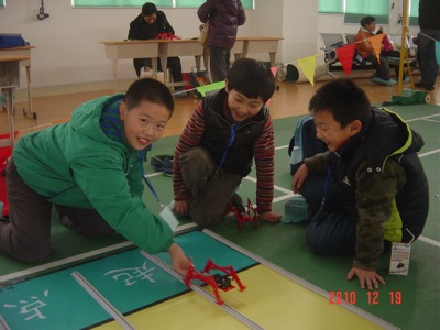
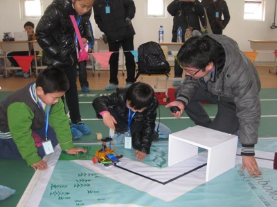
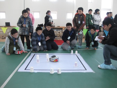
Photos from the new robot contest for kids in Shanghai called RoboMaster. Looks a lot of fun!
 ]]>
]]>
四轴飞行器进展
December 30th, 2010 § 3 comments § permalink
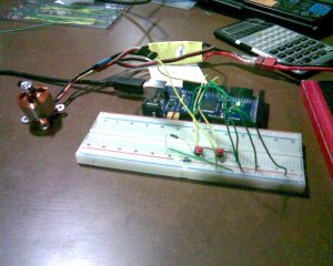 其实这个电路十分简单,就是两个按钮接入Arduino,然后Arduino输出PWM信号到电调,电调再输出电流到电机,从而就行成了按钮控制电机的一个装置。
不过,在完成这样一个小小的系统也经历了很多挫折。
首先,舵机还是电调都是通过PWM波进行控制的,比如下面这张图当中
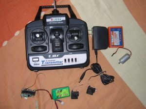 这个就是一般航模用的遥控器,接收机接收到射频信号后,将信号解调成PWM输出到舵机或者是电调中。所以电调和舵机都能够接收PWM信号,且信号格式是统一的。
但是,PWM信号到底是什么格式,频率多少,占空比多少,在网上查了查,却没有一个确切的数据。有个数据比就是futata的标准,pwm频率是50Hz, 脉冲宽度为920usec到2120usec,这样对应了舵机的0度到180度。
对于这个数值,我用51做了一个PWM的发生器,通过在电脑上输入角度(0到180度),然后产生一个特定的PWM波输出到舵机,就是下面这张图中的。
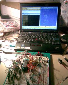 可是结果发现,舵机行程明显不足180度,只能勉强算是90左右,看来920usec-2120usec并不是对于舵机确切的控制数据,或者说对于除futaba以外的舵机的控制格式。
经过调试,发现要使舵机达到0度到180度的行程,PWM波的脉冲宽度要在800usec到2800usec之间。同时也有个有趣的现象。如果给舵机的信号线一个脉冲信号,宽度在800usec到2800usec之间,然后持续低电位,舵机会保持在该脉冲所对应角度不变,也就是说,PWM的频率是可以低于50Hz的。
回到Arduino上,Arduino自带Servo的库,可以编程实现从特定的角度输出特定的PWM波。就可以是用这样的PWM信号来控制电调,从而控制电机。这里有必须介绍一下电调的特点。我们是用的电调是比较廉价的新西达电调,但是它也带模式设定的功能,可以根据不同的场合来设定电调的工作模式。设定的过程就是,PWM信号为最高时,给电调上电。具体的设定过程可以在网上查到。经过实验发现Arduino输出角度为0的PWM信号根本不会对电调有任何影响,电调完全无视这个信号的存在-_-b。经过仔细思考后发现,会不会是因为电调是用的是futaba的PWM格式,而800usec或者Arduino最低的pwm信号对于电调来说过低,导致电调不能够辨认。
以下就是能够控制电机速度的程序代码
#include <Servo.h>
Servo myservo;
int pos = 0;
int buttonState = 0;
int lastButtonState = 0;
int currentAngle;
int MAX_ANGLE = 140;
int MIN_ANGLE = 100;
void setup()
{
 myservo.attach(9);
 pinMode(13, OUTPUT);
 pinMode(2, INPUT);
 pinMode(3, INPUT);
 currentAngle = 100;
}
void loop()
{
 buttonState = digitalRead(2);
 if (buttonState == HIGH)
 {
 digitalWrite(13, HIGH);
 if (currentAngle < MAX_ANGLE)
 {
 currentAngle = currentAngle + 1;
 }
 }
 else
 {
 buttonState = digitalRead(3);
 if (buttonState == HIGH)
 {
 digitalWrite(13, HIGH);
 if (currentAngle > MIN_ANGLE)
 {
 currentAngle = currentAngle - 1;
 }
 }
 }
 if (buttonState == LOW)
 {
 digitalWrite(13, LOW);
 }
 myservo.write(currentAngle);
 delay(30);
}
]]>
