 新车间开放日:休闲机器人的时代
时间: 2011年元月十六日,下午一点到五点
地点:徐汇区永嘉路50号新单位(近陕西南路)
费用: 免费
随着数字零件价格的降低加上丰富的开源机器人软件,DIY机器人已经可以当做事一个假日的休闲活动。这次的新车间开放日我们将介绍几个会员DIY的机器人和介绍一个将要举办的积极人竞赛。如果你对机器人有兴趣,请在这个周日加入我们,一起了解现代机器人的发展,一起讨论如何玩机器人。如果有小孩的话,非常欢迎他们一起来参加这个的活动。
– 关于HC Robot
http://code.google.com/p/hcrobot/
– 关于A.R.T.
http://xinchejian.com/?p=289
在这里注册
Robot Contest Kick Off- Xin Che Jian Open House: the coming of entertainment robots
Time: 13:00 – 17:00, Jan 16, 2011
Location: Xindanwei, 50 Yongjia Rd
Cost: Free, Open house
Building robots is fun and building robots to race is doubling the fun! The era of robot building as hobby has come and we plan to celebrate the beginning of this era with a festive robot contest. At this Xin Che Jian open house, we will present a few home built robots and the plan for a contest for discussion. Come and see how you can get involved! If you are a parent, bring the kids! We are sure they will love the robots!
Robots on site:
– HC Robot: open source home help robots
http://code.google.com/p/hcrobot/
– A.R.T.
http://xinchejian.com/?p=289
Register for the event here]]>
新车间开放日:休闲机器人的时代
时间: 2011年元月十六日,下午一点到五点
地点:徐汇区永嘉路50号新单位(近陕西南路)
费用: 免费
随着数字零件价格的降低加上丰富的开源机器人软件,DIY机器人已经可以当做事一个假日的休闲活动。这次的新车间开放日我们将介绍几个会员DIY的机器人和介绍一个将要举办的积极人竞赛。如果你对机器人有兴趣,请在这个周日加入我们,一起了解现代机器人的发展,一起讨论如何玩机器人。如果有小孩的话,非常欢迎他们一起来参加这个的活动。
– 关于HC Robot
http://code.google.com/p/hcrobot/
– 关于A.R.T.
http://xinchejian.com/?p=289
在这里注册
Robot Contest Kick Off- Xin Che Jian Open House: the coming of entertainment robots
Time: 13:00 – 17:00, Jan 16, 2011
Location: Xindanwei, 50 Yongjia Rd
Cost: Free, Open house
Building robots is fun and building robots to race is doubling the fun! The era of robot building as hobby has come and we plan to celebrate the beginning of this era with a festive robot contest. At this Xin Che Jian open house, we will present a few home built robots and the plan for a contest for discussion. Come and see how you can get involved! If you are a parent, bring the kids! We are sure they will love the robots!
Robots on site:
– HC Robot: open source home help robots
http://code.google.com/p/hcrobot/
– A.R.T.
http://xinchejian.com/?p=289
Register for the event here]]>
新车间开放日:休闲机器人的时代 Robot Contest Kick Off- Xin Che Jian Open House: the coming of entertainment robots
January 7th, 2011 § 0 comments § permalink
A.R.T. Glamour
January 6th, 2011 § 1 comment § permalink
 ]]>
]]>
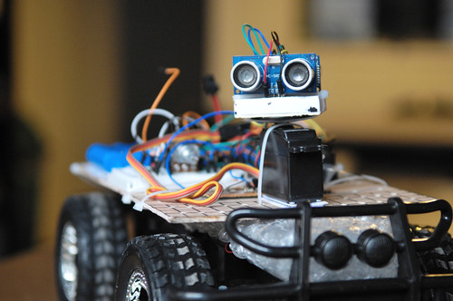
ART Platform v3, Control v4 and the future platform v4
January 3rd, 2011 § 3 comments § permalink
many iterations of both the software (the controller) after updating the platform (sensors+chassis) itself to have an additional ultrasonic sensor looking backward. So now, when I rotate the ultrasonic sensor, I read values in front (right side, angle looking right, looking forward and at angle to the left) and towards the back (left-side, side angle looking backward towards the left, angle straight on towards the back and angle looking backward towards the right). So six values in total… Having the servo rotate the sensors is necessary right now so as not to go over budget on the digital pins of the Arduino Dueminalove board as each of the two sensors require two signal cable (one for trigger and one for echo). I’ve done many changes and many tests but I’m not yet satisfied with the controller for that particular configuration and I still have ideas that I need to implement to make the robot behavior interesting… However, in the meantime, I’m also preparing for the next platform. I’m thinking of designing a circuit to select one ultrasonic sensor at a time out of four. Since two sensors cannot be triggered simultaneously (they would interfere with each other) I would want to trigger one at a time and then wait for the echo. To help with that task, I’ve discovered two wonderful OpenSource software:
- Fritzing: a very good design software that lets you design breadboard, schematic and final PCB layout with a library of parts (or very easy to create custom parts) in an optimized workflow
- Logic Gate Simulator: create and test logic gates design
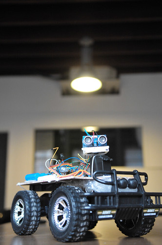
ARTv2 goes Ultrasonic!
December 30th, 2010 § 1 comment § permalink
Me: …since we don’t have many working sensors, I’m waiting for the ultrasonic sensors we ordered… BTW, Xu, any news about them? Xu: Oh, they’re at my desk! Me: screams like a little girl Xu: … ok, I’ll go get them now… So yeah, I finally got my 10 (!) ultrasonic sensors (HC-SR04) this evening, just in time as I had worked out how to control the servo to do sensor sweeps (left and right on 180 degrees). BTW, if you’re a Xinchejian member, please feel free to borrow one or two to try them out. They’re affordable (37RMB on Taobao or 5.60$USD), ridiculously easy to install and seem to work as advertised, although I haven’t benchmarked much. I’ve also spent quite a bit of time this evening on a reasonably workable controller with a state machine but only had time to test it once before I had to call it a day. I can probably use more sensors (on the sweeper, sideways, looking backward), but I’m thinking that I really need to combine them with infrared sensors as there’s a longer delay than infrared in detecting obstacles and they can work at angles simultaneously. Anyway, more testing and experiments are in order. [gallery]]]>
四轴飞行器进展
December 30th, 2010 § 3 comments § permalink
 其实这个电路十分简单,就是两个按钮接入Arduino,然后Arduino输出PWM信号到电调,电调再输出电流到电机,从而就行成了按钮控制电机的一个装置。
不过,在完成这样一个小小的系统也经历了很多挫折。
首先,舵机还是电调都是通过PWM波进行控制的,比如下面这张图当中
其实这个电路十分简单,就是两个按钮接入Arduino,然后Arduino输出PWM信号到电调,电调再输出电流到电机,从而就行成了按钮控制电机的一个装置。
不过,在完成这样一个小小的系统也经历了很多挫折。
首先,舵机还是电调都是通过PWM波进行控制的,比如下面这张图当中
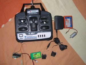 这个就是一般航模用的遥控器,接收机接收到射频信号后,将信号解调成PWM输出到舵机或者是电调中。所以电调和舵机都能够接收PWM信号,且信号格式是统一的。
但是,PWM信号到底是什么格式,频率多少,占空比多少,在网上查了查,却没有一个确切的数据。有个数据比就是futata的标准,pwm频率是50Hz, 脉冲宽度为920usec到2120usec,这样对应了舵机的0度到180度。
对于这个数值,我用51做了一个PWM的发生器,通过在电脑上输入角度(0到180度),然后产生一个特定的PWM波输出到舵机,就是下面这张图中的。
这个就是一般航模用的遥控器,接收机接收到射频信号后,将信号解调成PWM输出到舵机或者是电调中。所以电调和舵机都能够接收PWM信号,且信号格式是统一的。
但是,PWM信号到底是什么格式,频率多少,占空比多少,在网上查了查,却没有一个确切的数据。有个数据比就是futata的标准,pwm频率是50Hz, 脉冲宽度为920usec到2120usec,这样对应了舵机的0度到180度。
对于这个数值,我用51做了一个PWM的发生器,通过在电脑上输入角度(0到180度),然后产生一个特定的PWM波输出到舵机,就是下面这张图中的。
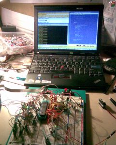 可是结果发现,舵机行程明显不足180度,只能勉强算是90左右,看来920usec-2120usec并不是对于舵机确切的控制数据,或者说对于除futaba以外的舵机的控制格式。
经过调试,发现要使舵机达到0度到180度的行程,PWM波的脉冲宽度要在800usec到2800usec之间。同时也有个有趣的现象。如果给舵机的信号线一个脉冲信号,宽度在800usec到2800usec之间,然后持续低电位,舵机会保持在该脉冲所对应角度不变,也就是说,PWM的频率是可以低于50Hz的。
回到Arduino上,Arduino自带Servo的库,可以编程实现从特定的角度输出特定的PWM波。就可以是用这样的PWM信号来控制电调,从而控制电机。这里有必须介绍一下电调的特点。我们是用的电调是比较廉价的新西达电调,但是它也带模式设定的功能,可以根据不同的场合来设定电调的工作模式。设定的过程就是,PWM信号为最高时,给电调上电。具体的设定过程可以在网上查到。经过实验发现Arduino输出角度为0的PWM信号根本不会对电调有任何影响,电调完全无视这个信号的存在-_-b。经过仔细思考后发现,会不会是因为电调是用的是futaba的PWM格式,而800usec或者Arduino最低的pwm信号对于电调来说过低,导致电调不能够辨认。
以下就是能够控制电机速度的程序代码
可是结果发现,舵机行程明显不足180度,只能勉强算是90左右,看来920usec-2120usec并不是对于舵机确切的控制数据,或者说对于除futaba以外的舵机的控制格式。
经过调试,发现要使舵机达到0度到180度的行程,PWM波的脉冲宽度要在800usec到2800usec之间。同时也有个有趣的现象。如果给舵机的信号线一个脉冲信号,宽度在800usec到2800usec之间,然后持续低电位,舵机会保持在该脉冲所对应角度不变,也就是说,PWM的频率是可以低于50Hz的。
回到Arduino上,Arduino自带Servo的库,可以编程实现从特定的角度输出特定的PWM波。就可以是用这样的PWM信号来控制电调,从而控制电机。这里有必须介绍一下电调的特点。我们是用的电调是比较廉价的新西达电调,但是它也带模式设定的功能,可以根据不同的场合来设定电调的工作模式。设定的过程就是,PWM信号为最高时,给电调上电。具体的设定过程可以在网上查到。经过实验发现Arduino输出角度为0的PWM信号根本不会对电调有任何影响,电调完全无视这个信号的存在-_-b。经过仔细思考后发现,会不会是因为电调是用的是futaba的PWM格式,而800usec或者Arduino最低的pwm信号对于电调来说过低,导致电调不能够辨认。
以下就是能够控制电机速度的程序代码
#include <Servo.h>
Servo myservo;
int pos = 0;
int buttonState = 0;
int lastButtonState = 0;
int currentAngle;
int MAX_ANGLE = 140;
int MIN_ANGLE = 100;
void setup()
{
 myservo.attach(9);
 pinMode(13, OUTPUT);
 pinMode(2, INPUT);
 pinMode(3, INPUT);
 currentAngle = 100;
}
void loop()
{
 buttonState = digitalRead(2);
 if (buttonState == HIGH)
 {
 digitalWrite(13, HIGH);
 if (currentAngle < MAX_ANGLE)
 {
 currentAngle = currentAngle + 1;
 }
 }
 else
 {
 buttonState = digitalRead(3);
 if (buttonState == HIGH)
 {
 digitalWrite(13, HIGH);
 if (currentAngle > MIN_ANGLE)
 {
 currentAngle = currentAngle - 1;
 }
 }
 }
 if (buttonState == LOW)
 {
 digitalWrite(13, LOW);
 }
 myservo.write(currentAngle);
 delay(30);
}
]]>
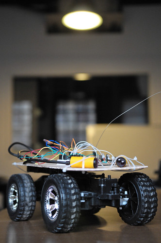
A.R.T. Version 2 (with instructions!)
December 30th, 2010 § 0 comments § permalink
Today I built a second new A.R.T. to test new configurations.
It’s also because it is a bit frustrating not to have a working version at all times for demos while I’m trying out new mechanical layouts… I took the opportunity to write down a detailed list of parts, tools and steps that I’ve checked in to github (note that I have not finished as I still have to solve the ranging sensor and write a new program):
https://github.com/rngadam/ART/blob/master/ART_Control3/BUILD.txt
See gallery for pictures…
[gallery link="file"] ]]>First successful autonomous run of A.R.T.
December 27th, 2010 § 1 comment § permalink
const int FORWARD =  2;
const int REVERSE =  3;
const int LEFT = 4;
const int RIGHT =  5;
const int INFRARED_FORWARD = A0;
const int INFRARED_REVERSE = A1;
const int MINIMUM_INFRARED_READING = 500;
int current_reverse = LEFT;
int alt_forward = RIGHT;
char current_state;
void setup() {
  pinMode(FORWARD, OUTPUT);
  pinMode(REVERSE, OUTPUT);
  pinMode(LEFT, OUTPUT);
  pinMode(RIGHT, OUTPUT);
  pinMode(INFRARED_FORWARD, INPUT);
  pinMode(INFRARED_REVERSE, INPUT);
  Serial.begin(9600);
}
char update_state(char state, int reason) {
  char previous_state = current_state;
  if(state != current_state) {
    current_state = state;
    Serial.print(current_state);
    Serial.println(reason);
  }
  return previous_state;
}
void loop(){
    // always check if we can go forward
    int value = analogRead(INFRARED_FORWARD);
    if(value >= MINIMUM_INFRARED_READING) {
        // maybe we were correcting, so check that
        char last_state = update_state('F', value);
        digitalWrite(current_reverse, LOW);
        digitalWrite(REVERSE, LOW);
        if(last_state == 'R') {
          // we just successfully exited a bad loop, turn for a bit for half a second
          digitalWrite(alt_forward, HIGH);
          digitalWrite(FORWARD, HIGH);
          delay(1000);
          digitalWrite(alt_forward, LOW);
        }
        digitalWrite(FORWARD, HIGH);
    } else {
      // otherwise, still correcting, keep off
      digitalWrite(FORWARD, LOW);
      // we want to try to find an alt path
      int value = analogRead(INFRARED_REVERSE);
      if(value >= MINIMUM_INFRARED_READING) {
        //still have some ability to go backward
        update_state('R', value);
        digitalWrite(current_reverse, HIGH);
        digitalWrite(REVERSE, HIGH);
      } else {
        // whooaah, even backward is not possible, we're stuck
        digitalWrite(current_reverse, LOW);
        digitalWrite(REVERSE, LOW);
        update_state('S', value);
      }
    }
}
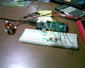
Wins:
- Wooden board and tie-wraps work exceptionally well to prototype the physical arrangement
- Using the breadboard to prototype the electronics also works well
- The Arduino “Vin” to provide current in the board header works very well (and can seamlessy switch between USB and that without resetting!)
- Sticking the RF transmitter board directly on the robot and controlling the motors with that from the Arduino works well
- The LED that comes on when an obstacle is detected by the infrared sensors is very useful for debugging (need to keep that in mind when using other sensors)
- It works!
- Uses Alkaline AA batteries (I want to switch to the exact same Rechargeable NiCad as the car uses)
- I spent too much time working with Sketchup instead of manually testing the mechanical design first (and then Sketchup)
- There’s not much around Xindanwei in terms of computer, electronic or small mechanical stores, so I should plan ahead to shop on Beijing road
- The infrared sensors that I found in the pile of stuff in Xinchejian work, but more like “on/off” sensors (don’t seem to have any linearity in the distance)
- No bumper (the infrared sensor was crashing into the walls…)
- Making an obstacle course big enough is annoying
- I had forgotten to make the holes to attach the sensors (more holes == better)
- No on/off switch so have to manually remove the connections to turn off power
- You can never have enough tie-wraps… We only had four at Xinchejian before I bought a pack of 500 for 15RMB (but really, worth about 5RMB)
- I need to learn how to solder… without blowing fuses…
Xinshanzhai [1]: Seeed Studio and Facilitate Open Innovation
December 26th, 2010 § 0 comments § permalink
Xinchejian kicked off the first of the “Xinshanzhai” series of talks and discussion on how “Shanzhai” micro manufacture efficiency combined with open innovation process and open source hardware will change how China innovate. We had the honor to have Eric Pan, CEO and Founder of Seeed Studio to give the talk “Facilitate Open Innovation – The Seeed Studio Approach” [Speech Slides].
 Seeed Studio was founded 3 years ago in Shenzhen to explore combining open source hardware and the electronics supply chain in Shenzhen. Today, Seeed Studio employes over 30 engineers and support staffs with over USD$1 million in annual revenue mainly from US, Europe and Japanese customers which are 98% of its business. Seeed does not yet focus on Chinese market as Eric points out that the tinkers/makers community in China has not yet matured enough for Seeed and there is not enough community.
Seeed Studio has so far depends on words of mouth of open hardware community for its marketing and will launch its first marketing campaign in 2011. The following is one of the first ads to be run in Make Magazine.
Seeed Studio was founded 3 years ago in Shenzhen to explore combining open source hardware and the electronics supply chain in Shenzhen. Today, Seeed Studio employes over 30 engineers and support staffs with over USD$1 million in annual revenue mainly from US, Europe and Japanese customers which are 98% of its business. Seeed does not yet focus on Chinese market as Eric points out that the tinkers/makers community in China has not yet matured enough for Seeed and there is not enough community.
Seeed Studio has so far depends on words of mouth of open hardware community for its marketing and will launch its first marketing campaign in 2011. The following is one of the first ads to be run in Make Magazine.
 Seeed’s current focus is to grow its WISH platform described by Eric as a ecosystem to support open source hardware designers to better manage the product life cycle. WISH platform let designers and users propose requests and new design and through the community voting and pre-ordering process to help to bring products to the market. The process is best illustrated by this slide from the speech. Seeed also works with partners sites such as Dangerous Prototypes to promote the platform.
 Eric’s 30 minutes talk was followed by over 2 hours of heated discussion on the topics of open source hardware, innovation and manufacture. The talk and discussions were livecast on Sina Weibo by Steven Cheng under #新山寨#.
]]>
Eric’s 30 minutes talk was followed by over 2 hours of heated discussion on the topics of open source hardware, innovation and manufacture. The talk and discussions were livecast on Sina Weibo by Steven Cheng under #新山寨#.
]]>
Xinshanzhai edition 1: Facilitate Open Innovation, the Seeed Studio Approach 新山寨第一期: 开源硬件与开放式创新
December 20th, 2010 § 2 comments § permalink
 Time: 3pm Dec 26, 2010
Location: Xin Che Jian, 2nd floor, Yongjia Rd 50 (close to Shaanxi Road South)
Cost: 30RMB for non-Xinchejian members, free of charge for Xinchejian members.
Seeed Studio is an open hardware facilitation company based in Shenzhen, China. Benefiting from local manufacture power and convenient global logistic system, we integrate resources to serve new era of innovation. Seeed also works with global distributors and partners to push open hardware movement.
We design modular electronics for quick prototyping and small scale projects, which could be found at Bazaar. It also carries inventories from community innovators, we help people make, distribute their designs and collect the revenue. It’s a win-win situation and taking a shape towards an ecosystem. By working with us, innovators could focus on the designs, provide better support to the user and promote the product. Seeed Studio or similar service provider could get more traffic and bring up other product sales.
The manufacture part of hardware involves a lot details. We provide Propagate service to facilitate the process. Innovator send finished prototype with manufacturing files including Gerber file, BOM, test plan and other requirements. Our engineering team will validate and integrate the design into small batch production line. All products will be tested and packed under instruction. Innovators could also view current manufacture and distribution status from propagate. After deducting the manufacture costs, profit will be returned to innovators when inventory sold out.
To estimate the popularity before investing manufacture, innovators could post the idea or prototype to Wish. The community would vote, comment and collaborate on projects. You could also join interested groups to see what’s hot being worked on. By participating Wish, ideas with many votes could convert the popularity into coupons to purchase product or service. The idea poster could also share some coupon to the valuable commenter as appreciation.
Products and service info are hosted at a wiki called Garden. Feel free to add your guide, project or yourself as a freelancer.
About the speaker
Eric Pan, founder and director of Seeed Studio, grew up with DIY culture in China. He graduated as an EE bachelor from Chongqing University, with experiences and prizes from national wide contests of MCU, Embe dded Design, Robotics, and English skills. He first joined Intel in Chengdu as a FCBGA product Engineer whose main job includes quality control and new product integration. Then he worked at Beamstream LLC as international sourcing manager on system solutions. He established Seeed Studio since 2008 from bare ground and now turning it into an open source hardware facilitator with 30+ employee.
新山寨第一期: 开源硬件与开放式创新
时间:2010年12月26日下午3点
地点:徐汇区永嘉路50号2楼新车间 (靠近陕西南路)
费用:新车间会员免费, 非新车间会员每人30元
Seeed Studio 是一个位于深圳的开源硬件生产公司. 得益于本土制造业的巨大力量以及便利的全球物流系统. 我们整合不同资源从而服务于新纪元创新时代. Seeed也与全球分销商和合作伙伴合作共同推动开源硬件的前进.
Eric Pan 是Seeed studio 的创始人, 他从小受DIY文化影响. 他毕业于重庆大学,获得了电子工程学士学位. 他在微型计算机, 嵌入式设计, 机器人, 英文技能领域都有丰富经验集获奖. 他的第一份工作是在成都intel 担当FCBGA 产品工程师. 其主要工作是腹侧质量控制和新产品整合开发. 随后他在Beamstream LLC 工作担任国际采购经理. 在2008年他创立了Seeed studio —从零起点开始到现在拥有30名员工的开源硬件生产中心.
更多信息可以参考 http://seeedstudio.com/]]>
Time: 3pm Dec 26, 2010
Location: Xin Che Jian, 2nd floor, Yongjia Rd 50 (close to Shaanxi Road South)
Cost: 30RMB for non-Xinchejian members, free of charge for Xinchejian members.
Seeed Studio is an open hardware facilitation company based in Shenzhen, China. Benefiting from local manufacture power and convenient global logistic system, we integrate resources to serve new era of innovation. Seeed also works with global distributors and partners to push open hardware movement.
We design modular electronics for quick prototyping and small scale projects, which could be found at Bazaar. It also carries inventories from community innovators, we help people make, distribute their designs and collect the revenue. It’s a win-win situation and taking a shape towards an ecosystem. By working with us, innovators could focus on the designs, provide better support to the user and promote the product. Seeed Studio or similar service provider could get more traffic and bring up other product sales.
The manufacture part of hardware involves a lot details. We provide Propagate service to facilitate the process. Innovator send finished prototype with manufacturing files including Gerber file, BOM, test plan and other requirements. Our engineering team will validate and integrate the design into small batch production line. All products will be tested and packed under instruction. Innovators could also view current manufacture and distribution status from propagate. After deducting the manufacture costs, profit will be returned to innovators when inventory sold out.
To estimate the popularity before investing manufacture, innovators could post the idea or prototype to Wish. The community would vote, comment and collaborate on projects. You could also join interested groups to see what’s hot being worked on. By participating Wish, ideas with many votes could convert the popularity into coupons to purchase product or service. The idea poster could also share some coupon to the valuable commenter as appreciation.
Products and service info are hosted at a wiki called Garden. Feel free to add your guide, project or yourself as a freelancer.
About the speaker
Eric Pan, founder and director of Seeed Studio, grew up with DIY culture in China. He graduated as an EE bachelor from Chongqing University, with experiences and prizes from national wide contests of MCU, Embe dded Design, Robotics, and English skills. He first joined Intel in Chengdu as a FCBGA product Engineer whose main job includes quality control and new product integration. Then he worked at Beamstream LLC as international sourcing manager on system solutions. He established Seeed Studio since 2008 from bare ground and now turning it into an open source hardware facilitator with 30+ employee.
新山寨第一期: 开源硬件与开放式创新
时间:2010年12月26日下午3点
地点:徐汇区永嘉路50号2楼新车间 (靠近陕西南路)
费用:新车间会员免费, 非新车间会员每人30元
Seeed Studio 是一个位于深圳的开源硬件生产公司. 得益于本土制造业的巨大力量以及便利的全球物流系统. 我们整合不同资源从而服务于新纪元创新时代. Seeed也与全球分销商和合作伙伴合作共同推动开源硬件的前进.
Eric Pan 是Seeed studio 的创始人, 他从小受DIY文化影响. 他毕业于重庆大学,获得了电子工程学士学位. 他在微型计算机, 嵌入式设计, 机器人, 英文技能领域都有丰富经验集获奖. 他的第一份工作是在成都intel 担当FCBGA 产品工程师. 其主要工作是腹侧质量控制和新产品整合开发. 随后他在Beamstream LLC 工作担任国际采购经理. 在2008年他创立了Seeed studio —从零起点开始到现在拥有30名员工的开源硬件生产中心.
更多信息可以参考 http://seeedstudio.com/]]>
A.R.T., PWM and RF
December 20th, 2010 § 0 comments § permalink
A.R.T.: Autonomous Robot Toy ^_^
- Forward: 16 pulses
- Reverse: 40 pulses
- Forward/Left: 28 pulses
- Forward/Right: 34 pulses
- Reverse/Left: 52 pulses
- Reverse/Right: 46 pulses
- RC control is 2.1 ms HIGH + 0.7ms LOW for a total of 2.8ms.
- This represents a duty of 2.1/2.8 = 75% duty cycle and a frequency of 1/0.00028 = ~3571 Hz.
- Pulse segment duty cycle is 50% (since pulse = interval) with a frequency of 1s/1.4ms (0.7ms+0.7ms) 714Hz.
- 1: 2240
- 8: 280
- 64: 35
- 256: 8.75
- 1024: 2.1875
- 1: 11200
- 8: 1400
- 64: 175
- 256: 43.75
- 1024: 10.9375